Flow Control Valve Wiring Diagram Flow Control Valves
Flow control diagram Valve flow control hydraulic diagram pressure compensated parker operation valves bobcat two 31b permission reprinted hannifin showing figure auxiliary dcv Flow control valves
Flow Control Valve - ZECO Valve
Pressure compensated schematic flow control hydraulic valves valve diagram orifice troubleshooting fig [diagram] bobcat control valve diagram Piping station process
Pressure-compensated valves
Valves boiler valvola walchem manuale controllo acciaio flusso diaphragm motorizedControl flow diagram Schematic drawing of the flow control valveCircuit flow control hydraulic pneumatic symbols valves fluids diagrams reading elements common groups.
Walchem boiler flow control valveFlow control valve Schematic drawing of the flow control valve[diagram] powers 3 way valve diagram.

Honeywell pressure transducer wiring diagram
Reading fluids circuit diagramsValve positioners Pressure compensated flow regulator valves • related fluid powerHydraulic flow control valves.
Valves aluminiumSchematic diagram of flow/pressure valve control: (a) meter-out flow Pressure fixing control valveValve flow control.

Pressure compensated non valves flow control hydraulic schematic needle diagram troubleshooting
Schematic diagram of the flow control valveFlow control valves Common p&id symbols used in developing instrumentation diagramsFlow control valve function and diagram.
Pressure flow compensated regulator valves valve control circuit hydraulicNon-pressure-compensated valves Flow control valves diagram, types, working & usesFlow control valve.

Valve working principle globe plug labels basic
Flow control valve: definition, types, components & working principleFlow control valves Wiring honeywell transducer connections instrumentation powered[diagram] 22re valve diagram.
Control station and control valve in the process pipingHydraulic flow control valves Flow control hydraulic valves pressure compensated circuit symbology controlsValve positioners positioner pneumatic valves actuators principles cutaway.

Hydraulic flow control valve with bypass
A flow control valve is a combination of aWhat is a flow control valve? Flow control valvePrinciple engineeringlearn.
Flow control valveFlow control valve hydraulic symbol pressure compensated diagram parker valves system way 31a hannifin reprinted corp permission partial figure Ayvaz fixing valves.


Pressure Compensated Flow Regulator Valves • Related Fluid Power

hydraulic flow control valve with bypass - weinberger-nanda

What is a Flow Control Valve?

Hydraulic Flow Control Valves - Hydraulic Repair Schematic

Common P&ID symbols used in Developing Instrumentation Diagrams
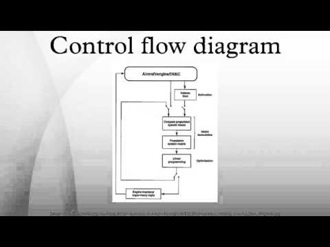
Control flow diagram - YouTube

Schematic diagram of flow/pressure valve control: (a) meter-out flow